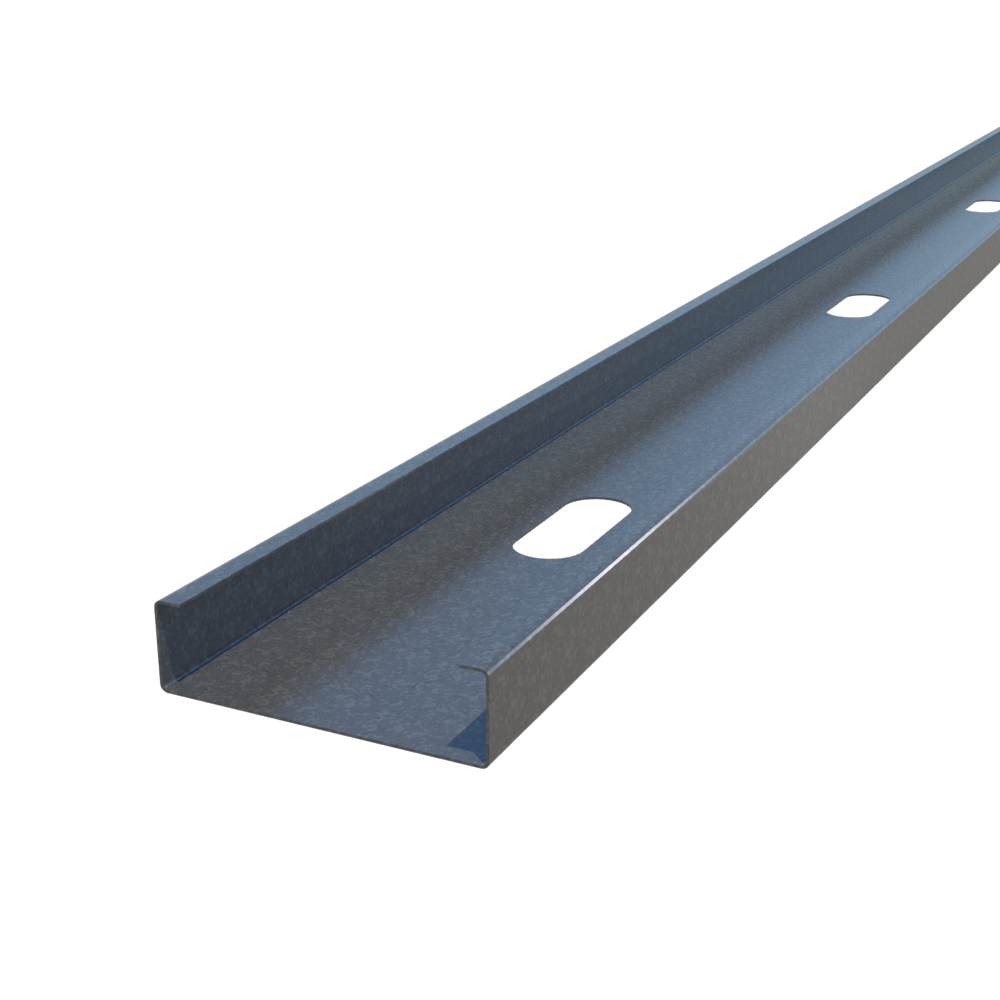
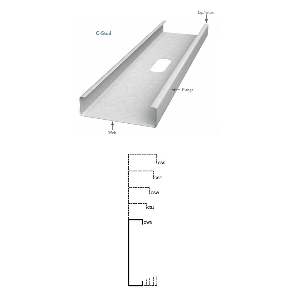
ClarkDietrich Cold-Formed Steel C-Studs (C-Series™)
Cold-Formed / Light-Gauge C-shaped framing members for axial load-bearing walls, curtain walls, tall interior partitions, floor joists and roof truss assemblies.
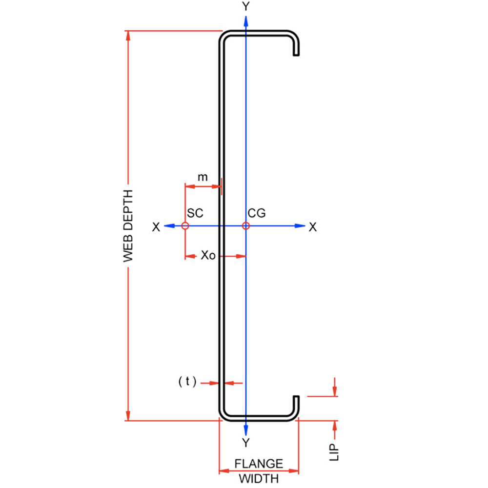
ClarkDietrich studs are made in a variety of flange widths to meet different applications.
Find the system you need with:
ClarkDietrich iTools - Structural Stud Lookup Tool
- Standard Web Size: 2-1/2” (250S), 3-1/2” (350S), 3-5/8” (362S), 4” (400S), 5-1/2” (550S), 6” (600S), 8” (800S), 10” (1000S), 12” (1200S), 14” (1400S)
- Flange Sizes: 1-3/8”, 1-5/8”, 2”, 2-1/2”, 3”.
- Thickness: 33 mils (20ga), 43 mils (18ga), 54 mils (16ga), 68 mils (14ga) and 97 mils (12ga).
- 33mil (20ga) and 43mil (18ga) framing products are produced with 33ksi steel.
- 54mil (16ga), 68mil (14ga) and 97mil (12ga) products are produced with 50ksi steel unless otherwise noted.
- Standard coating: CP60 (G60, CP90 & G90 available) Per AISI S240
- Additional member depths of 7-1/4", 9-1/4", 11-1/2", 13-1/2" and 14" are also available.
- All studs are color coded for easy identification.
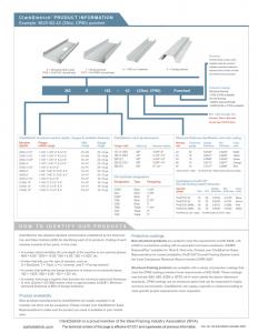
ClarkDietrich S137 (CWN) member have a 1-3/8" flange and 3/8" return and are used to support the exterior skin or cladding material (metal, stone, tile, glass, etc.) and the wind loads to which they are subjected.
ClarkDietrich S162 (CSJ) members have a 1-5/8" flange and a 1/2" return and are considered the industry standard. S162 members are preferred for most curtain wall applications. They also provide the vertical strength necessary for demanding load-bearing structural applications and sufficient strength for many joist applications.
ClarkDietrich S200 (CSW) members a 2" wide flange and a 5/8" return that provides a larger bearing surface for attaching sub-flooring or sheathing materials. This framing member is also used in axial load-bearing wall assemblies.
ClarkDietrich S250 (CSE) members have a 2-1/2" wide flange and a 5/8" return and are used in floor joist assemblies and heavy loading conditions.
ClarkDietrich S300 (CSS) members have a 3" flange and a 5/8" return and are used in very heavy loading and long spanning conditions.
See ClarkDietrich's Product Identification sheet for more on how to identify our products.
Full structural framing technical design guide
While this Design Guide Catalog is quite comprehensive, it does not completely cover our vast and growing lineup of products or design tables. To keep the catalog from being overloaded, it only includes half the design tables our online tools can offer. Please consider using ClarkDietrich iTools.
Structural Studs, may be used in a variety of applications and designs. While most conditions require the expertise of a design professional, many systems can be selected based on tabulated data or design tools. Locate the required assembly below and follow the instructions for selecting the proper design criteria.
ClarkDietrich Cold-Formed Steel C-Studs FAQs
Interior Walls w/Structural Framing (Nonstructural / Non-load bearing)
Design Tools:
Limiting Height Tables:
Typically ProSTUD Drywall Framing is used for interior walls but the use of structural framing may be needed to meet taller requirements. Interior nonstructural (non-load bearing) walls calculated in the Structural Stud Lookup Tool and Limiting Height Tables are limited to a superimposed axial load, exclusive of sheathing materials, of not more than 100 lb/ft, or a superimposed axial load of not more than 200 lbs.
Lateral Load / Design Load
Nonstructural (Non-load bearing) interior walls must be designed to withstand a minimum of 5 psf lateral load (perpendicular to the wall) for interior pressure as required by the International Building Code. Check your projects Architectural Specifications and/or drawings for the minimum design load required. Loads of 7.5psf and 10psf are typically used for shaftwalls or interior lobby walls located in floors with multiple exterior doors.
Deflection
The main purpose of specifying an allowable stud lateral deflection for interior wall framing is actually for determining what is an acceptable deflection for the wall facing materials. Sheathing and Finish materials require a minimum stiffness to prevent cracking. The required stiffness for the finish material is achieved by the specified deflection limit. Check with your projects Architectural Specifications and/or drawings for the lateral deflection required for a given wall facing material. Interior walls typically require a minimum lateral deflection of L/240. Some finishes such as tile or thin stone may require a higher deflection limit like L/360 or even L/600. We do not recommend using L/120 for walls taller than 10 feet.
For example a 10’ wall at L/120 (L = Length in inches, divided by 120) could have a lateral deflection of (10x12/120) = 1"
Limiting Heights
Limiting heights are based on continuous lateral support (gypsum wallboard) on each flange over the full height of the stud. If wallboard does not run the full height of the stud, lateral bracing may be required. Contact ClarkDietrich Technical Services to help determine spacing of the lateral bracing above the wallboard.
See all design notes on the bottom of the lookup tool and tables.
Exterior Curtain Walls
Design Tools:
- ClarkDietrich iTools - Structural Stud Lookup Tool
- For complex Curtain Wall systems, use our Curtain Wall Sizing Webform to submit to our Tech Team.
Limited Height Tables:
Curtain Wall Framing Systems support the exterior skin or cladding of commercial and industrial buildings. The studs for these framing systems must be able to withstand:
- The weight of the cladding material (metal, stone, tile, etc.).
- The wind loads to which they will be subjected.
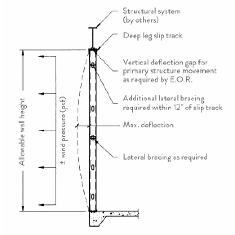
Exterior curtain walls are non-axial load bearing and must be designed to withstand the highest lateral loads, wind or seismic, prescribed by the building code for the particular construction location and type. Limited heights in the above lookup tool and tables are for single span systems only. It is recommended to have a vertical deflection gap between the top of the stud and top track for primary structure movement as required by the E.O.R. A deep leg deflection track system is used in this condition.
Lateral Load / Design Load
Exterior curtain walls must be designed to withstand the highest lateral loads anticipated for the particular construction location and type. Wind pressures can be found in the project's structural drawings under the “general notes” section. Required lateral loads for design must be provided by the E.O.R. or the Specialty Engineer.
Load/Span Table Wind Pressure Notes
Historically there have been differences in the design wind pressures determined through different versions of the model building codes. Older versions of the codes provided service level loads (ASD) while newer versions provide strength level loads (LRFD). Since IBC 2012/ASCE 7-10 design wind pressures have been determined via strength level (LRFD) loads. The load/span tables that follow are based on service level (ASD) wind loads. Therefore, to properly use the load/span tables in this catalog, multiply the IBC 2021/ASCE 7-16 design wind pressures by 0.6 (reference section 2.4 ASCE 7-16) prior to entering the load/span tables.
Example:
- ASCE 7-16 Calculated Design Wind Pressure = 25psf (strength level loads, LRFD)
- Convert to service level load (ASD) = 25psf x 0.6 = 15psf
- Use 15psf as the Pressure Value used in this table to determine the member span
The load/span tables that follow are based on service level (ASD) wind loads. If the wind load being used meets this criterion, it does not need to be modified prior to using the tables.
Deflection
The main purpose of specifying an allowable stud deflection for curtain wall framing is actually for determining what is an acceptable deflection for the wall facing materials. A metal stud is ductile and therefore can perform at a wide range of deflections. Wall facing materials tend to be more brittle (Brick, Stucco or EIFS), and thus have a more stringent maximum allowable deflection. The project architect or project specifications should note what the allowable deflection is for a given wall facing material.
Typical Deflection Requirements: (L = Length in inches)
- L/240 Exterior siding or EIFS
- L/360 Exterior stucco
- L/600 Exterior brick or stone
- L/720 Exterior brick or stone
For example a 20’ wall at L/240 (L = Length in inches, divided by 240) could have a lateral deflection of (20x12/240) = 1”.
Limiting Heights
Limiting heights are based on continuous lateral support (rigid sheathing) on each flange over the full height of the stud. Horizontal structural bridging (or bracing) is defaulted to be at 4 ft. on center for the purposes of the values shown in the lookup tool and tables. The actual bridging that is ultimately provided is to be determined by the licensed specialty engineer responsible for the cold-formed steel design for the given project. Contact ClarkDietrich Technical Services to help determine maximum spacing of the lateral bracing.
Adding additional horizontal bridging will not reduce the actual deflection in the wall. To reduce the deflection of a wall stud, either a heavier member is required or an intermediate structural support must be provided.
See all design notes on the bottom of the lookup tool and tables.
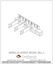
Interior and Exterior Load Bearing Walls
Design Tables:
Load-bearing walls must be capable of handling vertical loads even when subjected to lateral loads from wind or another force. The following tables identify the axial (vertical) load that can be supported by each member under given lateral load conditions.
Need higher performance than conventional “C” shaped studs?
Heavy-Duty Stud (HDS®) alternative cost-effective framing system with superior strength. The superior strength and carrying capacity of the HDS means higher performance with fewer members. It eliminates box beam headers, stud-to-track nesting, built-up members for posts and jambs and has superior axial strength for load-bearing projects.
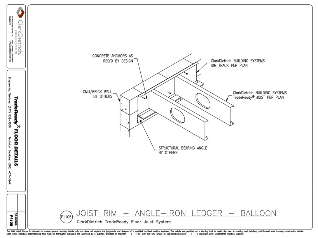
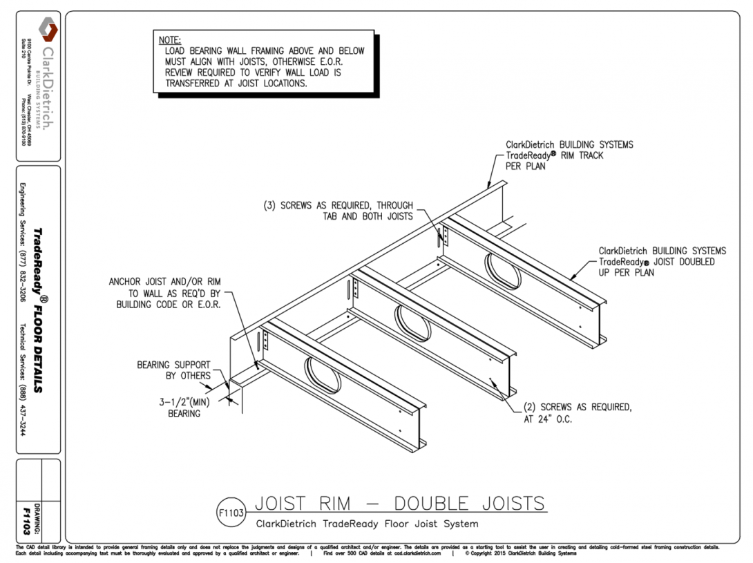
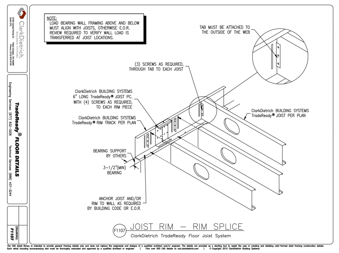
C-Joist Floor Framing
Design Tables:
- Floor Joist Span Tables
- Allowable Web Crippling Loads
- For complex Floor Joist systems, use our Floor Joist Sizing Webform to submit to our Tech Team.
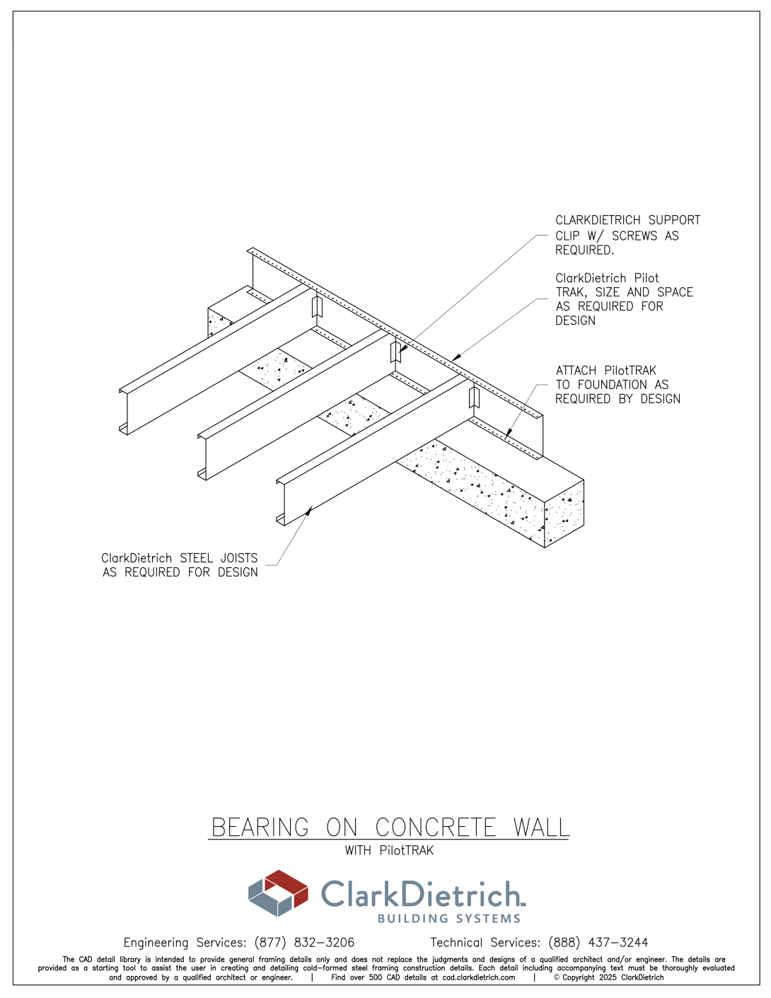
Depending on loads and spans, C-Joists are typically spaced at 12", 16", 19.2" or 24" on-center spacing. Structural track, usually in the same gauge as the joist, is used as rim or band enclosures. Joist to girder attachments are normally supported with joist hangers, EasyClip™ E-Series™ or S-Series™ support clips. Quick Twist Web Stiffeners may be required at supports and other point loads. Solid blocking and strapping is required to properly brace the floor assembly.
See Standard Joist System & Accessories for more
- Contact ClarkDietrich Technical Services at (888) 437-3244 for any questions on the design systems above.
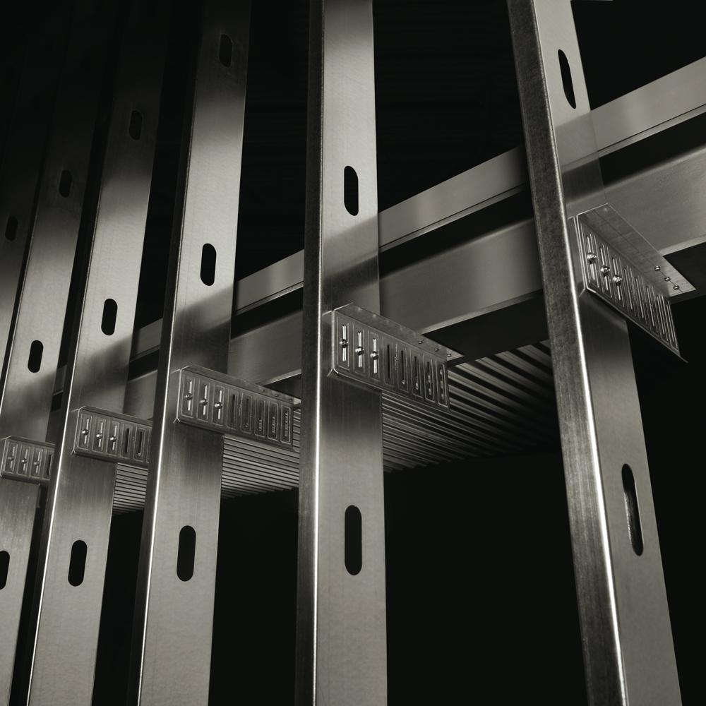
Easy installation of wiring, plumbing and bridging.
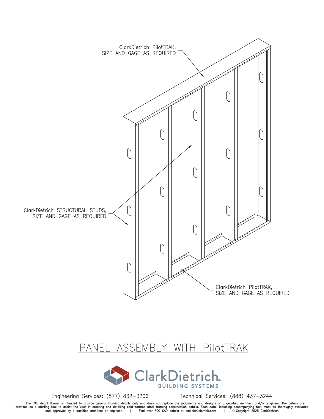
ClarkDietrich cold-formed C-studs, produced to AISI S240, for axial load-bearing and curtain-wall framing are pre-punched with punchouts at regular intervals—specifically designed to allow for rapid installation of pipes, electrical conduit and wall bridging.
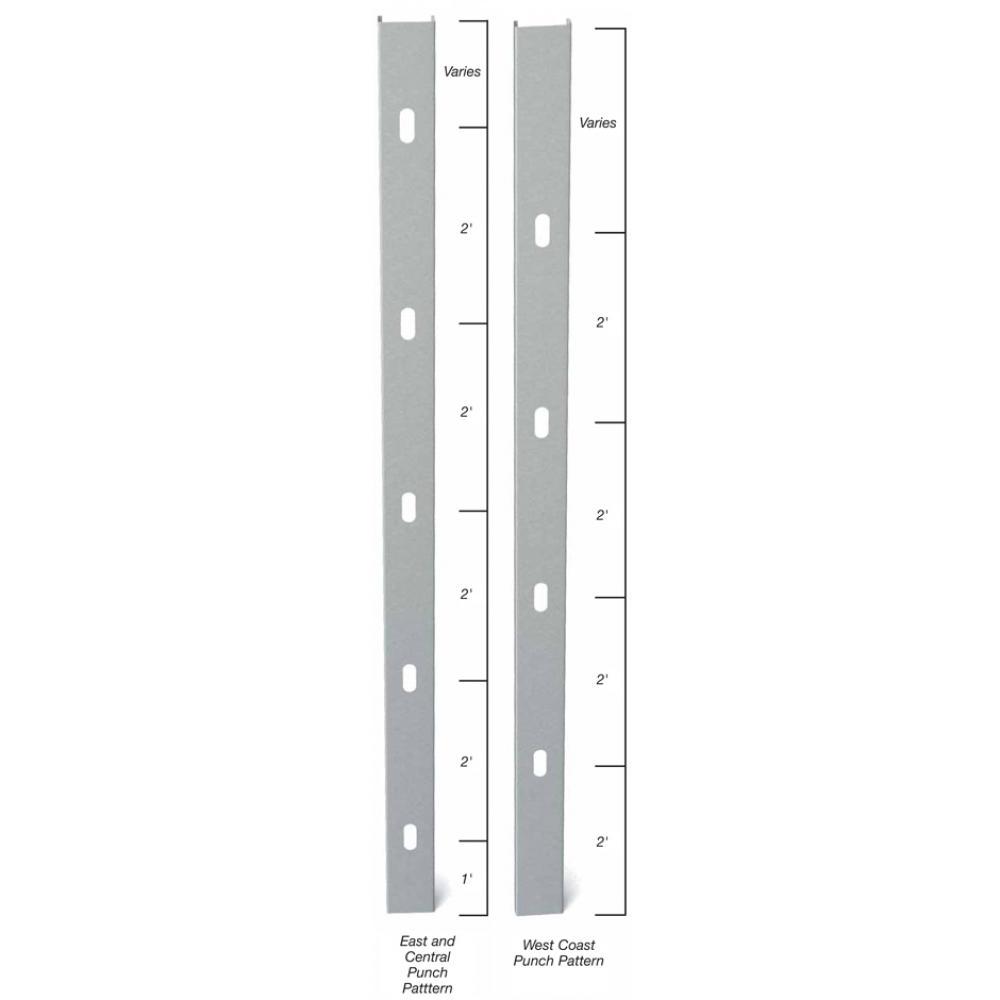
East Coast / Central punch spacing:
Center of punchouts are 12" from lead end, then 24" o.c.
West Coast punch spacing:
Center of punchouts are 24" from lead end, then 24" o.c.
Center of tail end punchout not less than 12" from end of stud.
Caution must be exercised when installing studs so knockouts align for bridging. Based on stud length, the distance the knockout falls from the tail end of the stud may not be the same from the lead end. To align punchouts, make sure to use the same end in the same direction consistently.
If lateral bracing is required for head-of-wall deflection track and a punchout is not spaced 12" from the top of stud, use strapping and blocking in lieu of CRC or Spazzer Bar lateral bridging.
If custom punchout patterns are required, contact ClarkDietrich Sales or local plant for requests.
Punchout Sizes
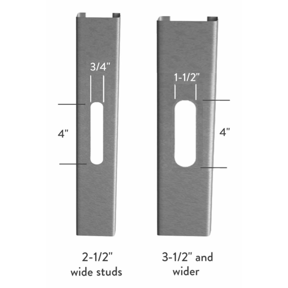
Standard punchout sizing is 1-1/2" x 4" in members 3-1/2" and wider. Members smaller than 3-1/2" are unpunched unless otherwise specified at time of order. If specified, members will be punched with a 3/4" x 4" knockout.
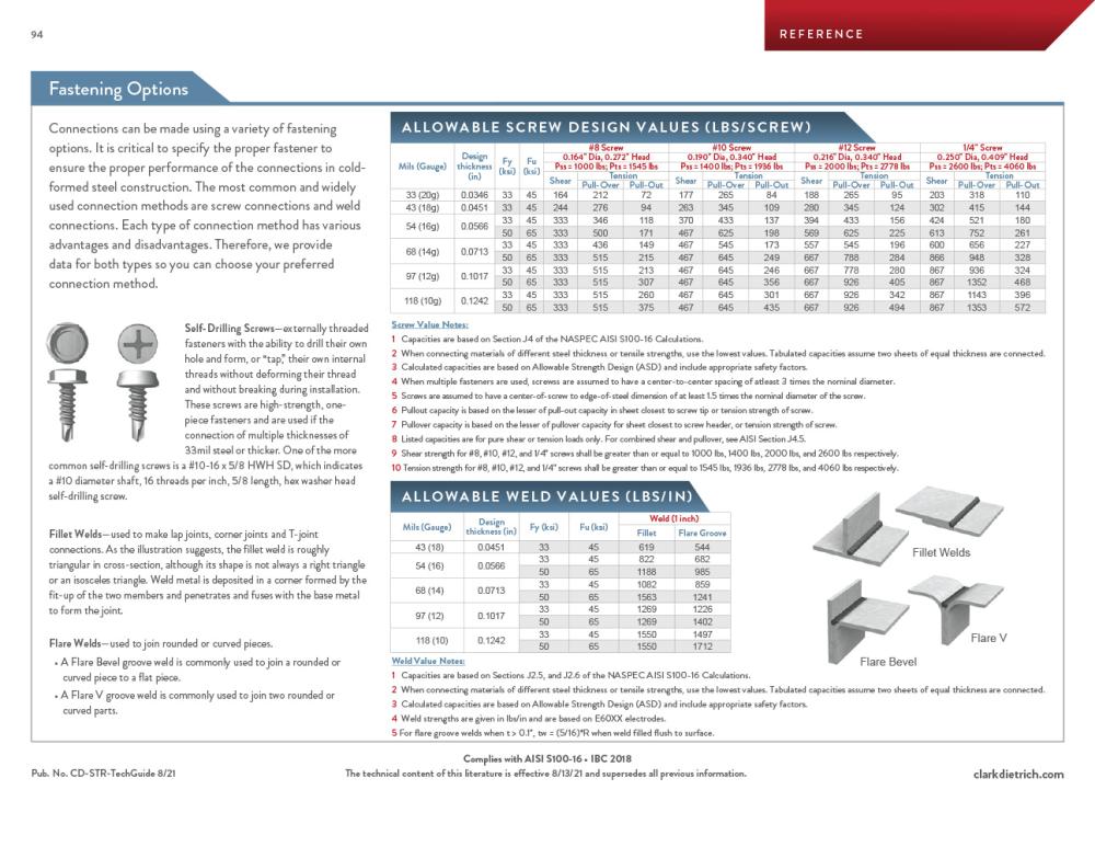
Structural Allowable screw & Weld design values (lb.)
Structural - Screw & Weld Allowable Loads
- Contact ClarkDietrich Technical Services at 888-437-3244 for questions about Screw Connections
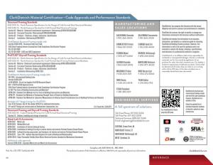
Code Approvals & Performance Standards
- AISI S100-16 (2020) w/S2-20 North American Specification for the Design of Cold-Formed Steel Structural Members
- AISI S240-20 North American Standard for Cold-Formed Steel Structural Framing
- (Compliant to ASTM C955, but IBC replaced with AISI S200 in IBC 2015, AISI S240 in IBC 2018)
- Section A3 Material - Chemical & mechanical requirements (Referencing ASTM A1003/A1003M)
- Section A4 Corrosion Protection (Referencing ASTM A653/A653M)
- Section A5 Products - Thickness, shapes, tolerances, identification
- Section C Installation - (Referencing ASTM C1007)
- AISI S202-20 Code of Standard Practice for Cold-Formed Steel Structural Framing
- Section F3 Delivery, Handling and Storage of Materials
- IBC 2024 International Building Code
- ICC-ES ESR-1166P Structural Studs and Track
- ESR-1166P Catalog ClarkDietrich Structural Technical Design Guide (6/1/24)
- Intertek CCRR-0206 Structural Studs and Track
- SFIA Stud Code Compliance Certification Program
- SDS For ASTM A1003 Steel Framing Products For Interior Framing, Exterior Framing and Clips/Accessories
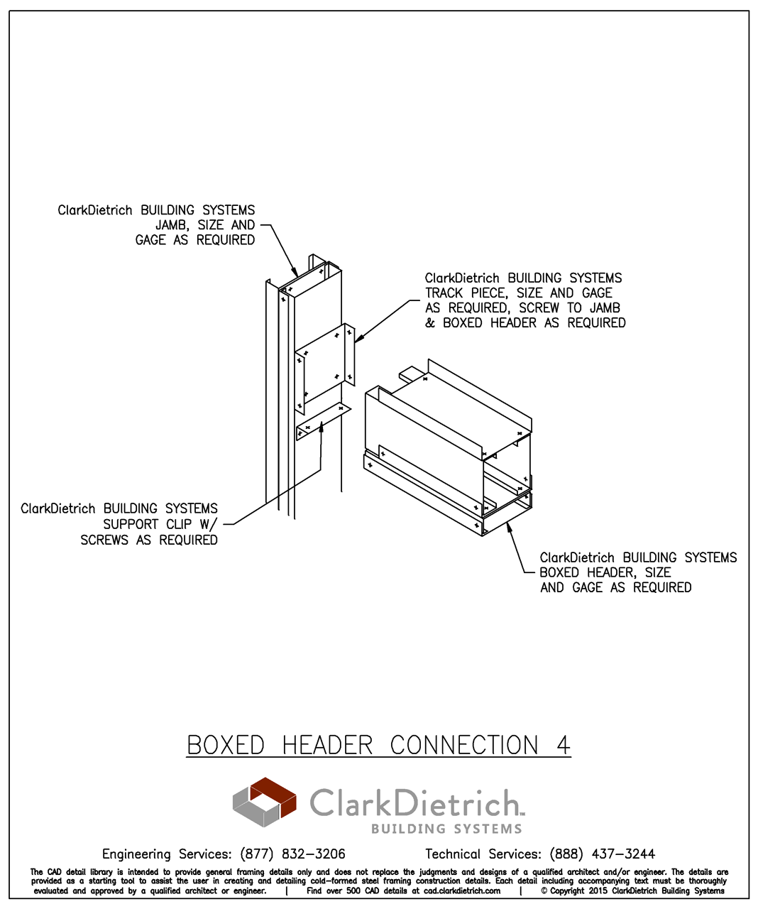
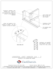
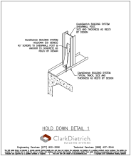
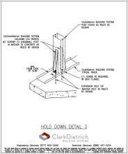
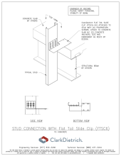
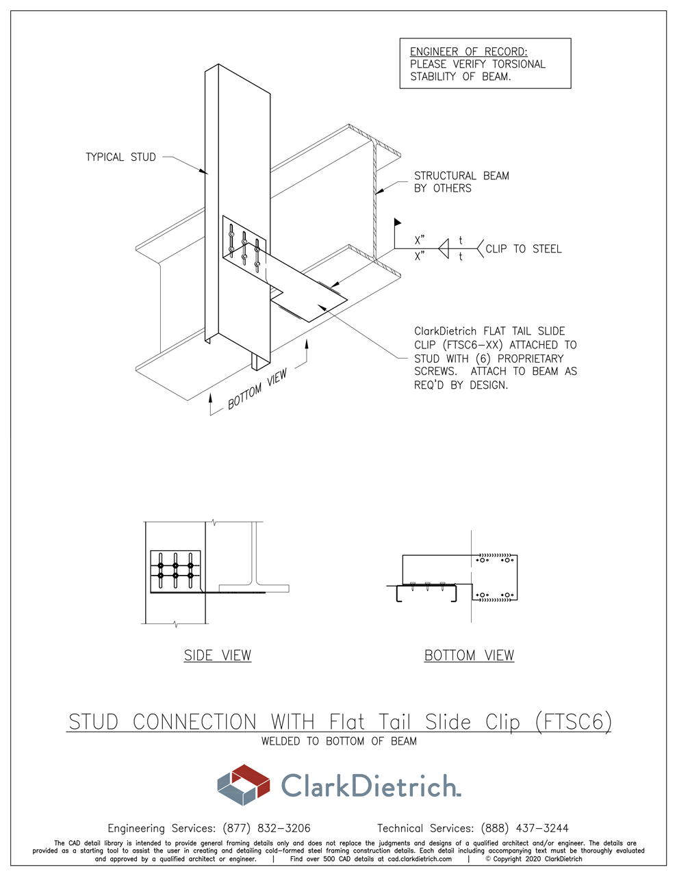
CAD Details
Note: to view all of ClarkDietrich's CAD details, visit the CAD Details Library.


ClarkDietrich SubmittalPro®
The Fastest way to find product information
Submittal sheets for the exact product you're looking for can be created by using ClarkDietrich's SubmittalPro® Product Submittal System.
Most common Structural submittals can be found below:
| Size / Thickness | Structural Stud | Track |
|---|---|---|
| 3-5/8" Web w/ 1-5/8" Flange 43mils (18ga) | 362S162-43-P | 362T125-43 |
| 3-5/8" Web w/ 1-5/8" Flange 54mils (16ga) | 362S162-54-P | 362T125-54 |
| 6 Web w/ 1-5/8" Flange 43mils (18ga) | 600S162-43-P | 600T125-43 |
| 6" Web w/ 1-5/8" Flange 54mils (16ga) | 600S162-54-P | 600T125-54 |
| Find all profiles in SubmittalPro® Product Submittal System | ||
- Contact ClarkDietrich Technical Services at 888-437-3244 for any questions about creating product submittals or using SubmittalPro.