


The premier floor joist system for both commercial and residential framing
TradeReady® steel joists are one of the primary components that make up the TradeReady® floor system. These joists feature large extruded holes that accommodate HVAC, mechanical, plumbing and sprinkler runs.
TradeReady® steel joists are precision manufactured from corrosion-resistant galvanized steel. Steel joists offer consistent quality, predictable performance and high strength to weight ratio, and they are dimensionally stable. They won’t expand, contract or shrink; they won’t warp, crack or twist. Steel joists integrate easily with other building materials such as structural steel, concrete, ICF and wood construction.
Joists can be ordered in standard lengths or to your exact specifications to minimize waste. Consult the ClarkDietrich Technical Design Team or the TradeReady® Steel Joist Design Guide for physical and structural properties, span charts and loading data.
- Span capacities to accommodate typical building layouts and floor/roof loads.
- Extruded hole sizes range from 4-1/4” oval to 10” round based on member depth
- Superior strength permits wider o.c. spacing
- Pre-cut to your exact specifications—no waste
- Available in 7-1/4”, 8”, 9-1/4”, 10”, 11-1/4”, 12” and 14” deep members
- Symmetrical flange sizes include 1-3/4” and 2”
- Eliminates soffit framing
- UL Listed assemblies
Accessory Products
For a full line of products that work with TradeReady see iTools Floor Framing Connections

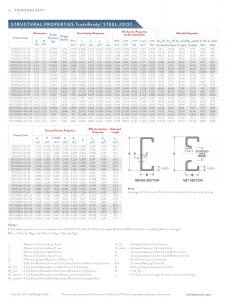
TradeReady 2022 joist and rim track section properties
Load Tables
- See the TradeReady® Steel Joist Design Guide for span charts and loading data.
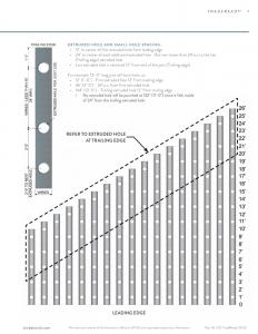
EXTRUDED HOLE SIZE
| EXTRUDED HOLE PER JOIST DEPTH | |||||||
|---|---|---|---|---|---|---|---|
| Joist Depth | 7-1/4" | 8" | 9-1/4" | 10" | 11-1/4" | 12" | 14" |
| Extruded Hole Height | 4-1/4" | 4-1/4" | 6-1/4" | 6-1/4" | 6-1/4" | ||
| Extruded Hole Width | 7" | 7" | 9" | 9" | 9" | ||
| Extruded Hole Diameter | 8" | 10" | |||||

Optional Small Hole Size and Pattern:
- 1-11/32" holes are commonly used for electrical and plumbing
- 5/32" holes for insulation support wire

Extruded Hole and Small Hole Spacing:
- 12" to center of first extruded hole from leading edge
- 24" to center of each additional extruded hole - But not closer than 24"o.c to the last (Trailing edge) extruded hole
- Last extruded hole is centered 12" from end of the joist (Trailing edge)
For example: 13'-0" long joist will have holes at:
- 12" (1'-0") - First extruded hole 12" from leading edge
- 36" (3'-0") - 24"o.c. from first extruded hole
- 144" (12'-0") - Trailing extruded hole 12" from trailing edge
- No extruded hole will be located at 132" (11'-0") since it falls inside of 24" from the trailing extruded hole

EXTRUDED HOLE LAYOUT PER JOIST LENGTH
Extruded hole layout for joists spanning 12'-0" through 26'-0" at 1-0" increments. Alternate/specific span capacities available to accommodate typical building layouts and floor/roof loads Alternate span lengths available. Contact ClarkDietrich Technical Sales or Engineering for assistance.

Installation
IN THE FIELD - Installing the ClarkDietrich TradeReady® Steel Floor System
- Check material against cut list.
- Check joist layout against plumbing and HVAC requirements.
- Install TradeReady® Rim Track. Set first tab on layout, subsequent rims are butted together continuing the layout.
- Build / install girders.
- Set joist across work area. Note the joist orientation-holes should line up.
- Install any required web stiffeners prior to setting joist as per plan when possible. Attach joist to intermediate bearing locations.
- Rotate hard side of joist to tab and screw attach through pre-punched tab holes.
- Attach joist to intermediate bearing locations.
- Install temporary bracing as needed.
- Install blocking/bridging and solid blocking as required.
- Attach sub flooring – glue over joist, rim and blocking and screw attach sheathing as per details.
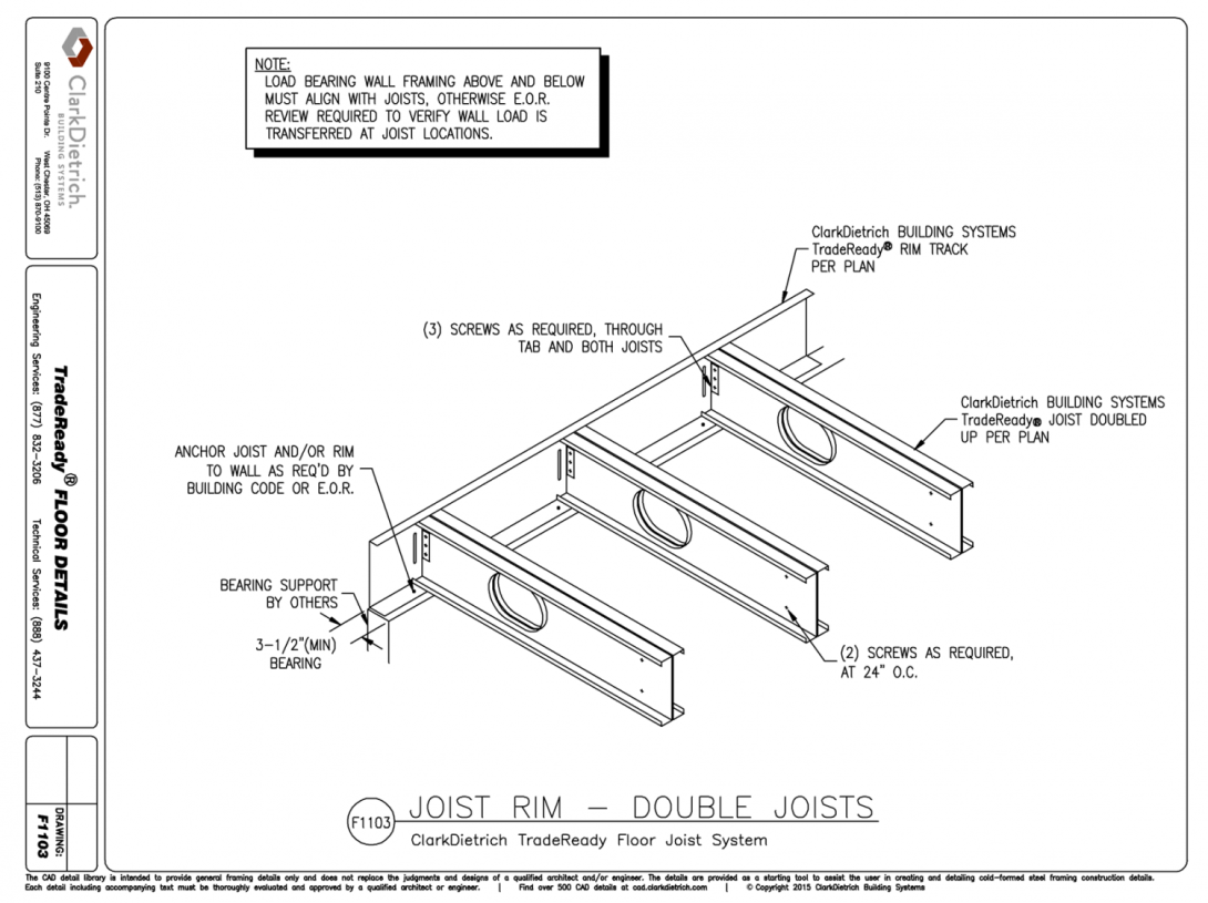
Platform Framing
A method of construction by which floor framing bears on load bearing walls that are not continuous through the story levels or floor framing.
Accessory installation instructions
For a full line of products that work with TradeReady see iTools Floor Framing Connections
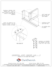
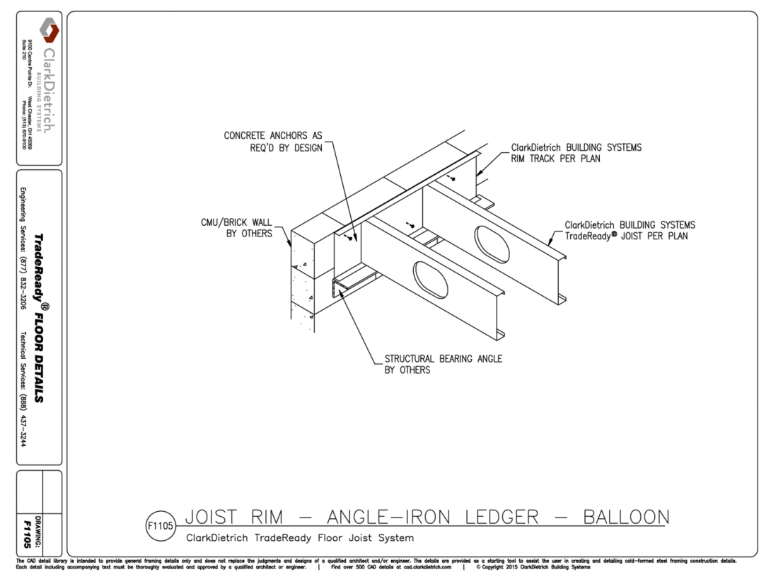
Balloon Framing
A method of construction where the studs run continuously from the sole plate to the rafter plate and intermediate floor framing is supported with a ribbon/ledger anchored to the side of the studs.
Installation Notes
- All framing components shall be cut squarely for attachment to perpendicular members or as required on angular fit against abutting members. Members shall be held positively in place until properly fastened.
- Temporary bracing shall be provided and remain in place until the structure is completely stabilized. Design of temporary bracing is not the responsibility of ClarkDietrich Building Systems.
- All field cutting of members must be done by sawing, plasma cutting or shearing. Torch cutting of coldformed members is unacceptable.
- It is the responsibility of the contractor to assemble the floor system in such a way that the extruded holes align for mechanical runs and to ensure that extruded holes do not occur within 12" of a bearing point due to field cutting.
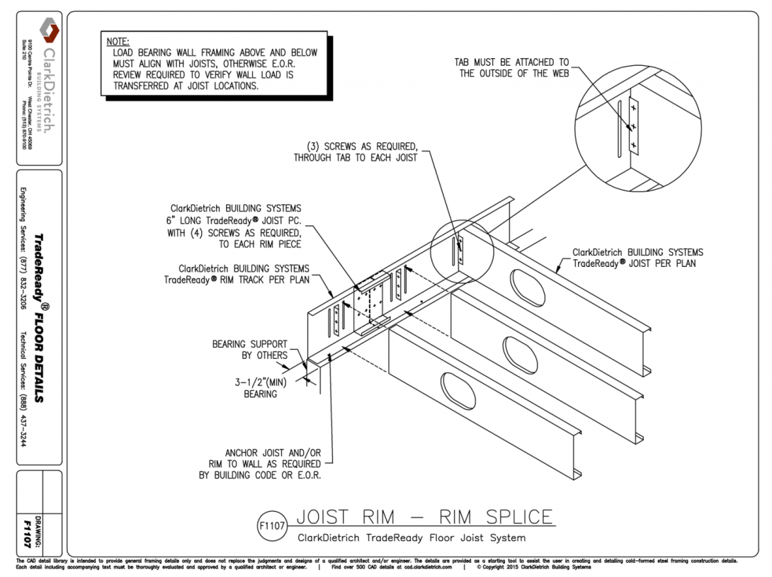
- No splices in studs, joists, or other load carrying members may be made without prior engineering review and specific details for any such splice(s).
- If additional holes are required, contact a licensed professional engineer for guidance before cutting.
- Mechanical bridging, spaced at the intervals required by design, shall be installed prior to the attachment of sheathing materials.
- Installation of sheathing, wallboard or any other collateral material shall be performed in accordance with the product manufacturer’s specifications, the current ASTM standard and/or guidelines outlined in the contract documents.
- For all tracks used in composite members such as beams and girders, the track must be installed as a single piece, no splicing permitted, unless otherwise noted.
- When support clips are used to attach a component to the primary structure, the support clip is to be fastened to the primary structure first. Then, the component should be brought to bear on the structure, and then fastened to the support clip.
- Support clips/hangers shall be installed per manufacturers instructions.

JOBSITE SAFETY
Always follow OSHA guidelines and safety requirements when they are applicable.
- DO NOT walk on unbraced joist. Injury may result.
- DO NOT load floor decking before sheathing and bracing is complete. Place loads only over load bearing members.
- Wear work gloves to protect hands from cuts and injuries when working with steel.
- Safety goggles are recommended when cutting steel or when fastening members.
- Cutting and welding galvanized steel can produce harmful fumes that can be hazardous to health and cause irritation to the respiratory system. Make sure all cutting and welding is done in a well-ventilated area.
- Use caution when working with steel when wet. Steel members may be slippery and cause injuries if not properly handled.
STORAGE AND HANDLING
Proper storage and handling will ensure the structural integrity of steel framing members and components.
- TradeReady® Steel joist bundles should be stored level.
- DO NOT open bundles until time of installation. Use care when handling bundles and individual components to prevent injury to handlers or damage by forklift or crane.
- Twisting of steel joists, or applying loads to the joist when flat can damage the joist. Damaged steel joists should not be used.
- Never handle steel joist flat. Beginning with the unloading process, and throughout all phases of construction, care must be taken to avoid lateral and torsional bending of joists, which can cause damage to the steel joists.
Code Approvals & Performance Standards
- AISI S100-16 (2020) w/S2-20 North American Specification for the Design of Cold-Formed Steel Structural Members
- Direct Strength Method (DSM) utilized for calculating flexural strength
- AISI S240-15 North American Standard for Cold-Formed Steel Structural Framing
- Section A3 Material - Chemical & mechanical requirements (Referencing ASTM A1003/A1003M)
- Section A4 Corrosion Protection (Referencing ASTM A653/A653M)
- Section A5 Products - Thickness, shapes, tolerances, identification
- UL File Number CJFS.R21191 TDJ24 fire rated assemblies
- UL File Number CJFS.R21191 TDW24 fire rated assemblies
- SDS For ASTM A1003 Steel Framing Products For Interior Framing, Exterior Framing and Clips/Accessories
**Note - 7-1/4" and 8" deep members are not included in UL listings**
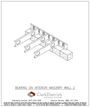
TradeReady® Framing and Construction Reference Details
The technical information contained in these CAD Details were prepared to assist professional engineers and architects in the use of the ClarkDietrich TradeReady® Steel Floor system and should be used only with the guidance and judgement of such architect or engineer.
The details provided should be reviewed for the following conditions:
Specific attachment requirements
- Attachments typically are screws, pins, nails, or other types of connectors.
- All attachment references should be reviewed for size, quantity, and manufacturer by the E.O.R.
- As a guide and reference only, some connection locations and size and quantity may be indicated by either a written note or by symbol (+) or both.
- Following the details section are specific connector values to assist in sizing the connections for some of the attachment details. For girder and beam attachments, please refer to the Support Clips tables.
Tables and Notes
- The tables reference specific construction conditions. The information in these tables should be addressed by the E.O.R.
- The sizing of clips and connectors may be effected.
- Notes are shown to address conditions that may be beyond the scope of the referenced detail. These conditions should be reviewed by the E.O.R.
Per Plan
- Many details are applicable to different building plans. Because specific member selection often changes from one application to another, several details include the note "per plan". The "per plan" citation may effect the framing members and the connectors used (see Specific Attachment Requirements above).
By Others
- The following details show general framing and construction conditions applicable to the ClarkDietrich TradeReady‚ Steel Floor System only. All other building components and their interaction with the TradeReady® floor system should be reviewed and specified by the E.O.R.
NOTES: Reference all notes in the Installation tab of the product page.
CAD Details
Note: to view all of ClarkDietrich's CAD details, visit the CAD Details Library.


ClarkDietrich SubmittalPro®
The Fastest way to find product information
Submittal sheets for the exact product you're looking for can be created by using ClarkDietrich's SubmittalPro® Product Submittal System.
TradeReady submittals can be found below:
| Joist Size / Thickness | Floor Joist |
|---|---|
| 7-1/4" Web w/ 1-3/4" Flange - 43mils (18ga) | 725TDJ24-175-43 |
| 7-1/4" Web w/ 1-3/4" Flange - 54mils (16ga) | 725TDJ24-175-54 |
| 7-1/4" Web w/ 1-3/4" Flange - 68mils (14ga) | 725TDJ24-175-68 |
| 7-1/4" Web w/ 1-3/4" Flange - 97mils (12ga) | 725TDJ24-175-97 |
| 8" Web w/ 1-3/4" Flange - 43mils (18ga) | 800TDJ24-175-43 |
| 8" Web w/ 1-3/4" Flange - 54mils (16ga) | 800TDJ24-175-54 |
| 8" Web w/ 1-3/4" Flange - 68mils (14ga) | 800TDJ24-175-68 |
| 8" Web w/ 1-3/4" Flange - 97mils (12ga) | 800TDJ24-175-97 |
| 9-1/4" Web w/ 1-3/4" Flange - 43mils (18ga) | 925TDJ24-175-43 |
| 9-1/4" Web w/ 1-3/4" Flange - 54mils (16ga) | 925TDJ24-175-54 |
| 9-1/4" Web w/ 1-3/4" Flange - 68mils (14ga) | 925TDJ24-175-68 |
| 9-1/4" Web w/ 1-3/4" Flange - 97mils (12ga) | 925TDJ24-175-97 |
| 10" Web w/ 2" Flange - 54mils (16ga) | 1000TDW24-200-54 |
| 10" Web w/ 2" Flange - 68mils (14ga) | 1000TDW24-200-68 |
| 10" Web w/ 2" Flange - 97mils (12ga) | 1000TDW24-200-97 |
| 11-1/4" Web w/ 1-3/4" Flange - 54mils (16ga) | 1125TDJ24-175-54 |
| 11-1/4" Web w/ 1-3/4" Flange - 68mils (14ga) | 1125TDJ24-175-68 |
| 11-1/4" Web w/ 1-3/4" Flange - 97mils (12ga) | 1125TDJ24-175-97 |
| 12" Web w/ 2" Flange - 54mils (16ga) | 1200TDW24-200-54 |
| 12" Web w/ 2" Flange - 68mils (14ga) | 1200TDW24-200-68 |
| 12" Web w/ 2" Flange - 97mils (12ga) | 1200TDW24-200-97 |
| 14" Web w/ 2" Flange - 68mils (14ga) | 1400TDW24-200-68 |
| 14" Web w/ 2" Flange - 97mils (12ga) | 1400TDW24-200-97 |
- Contact ClarkDietrich Technical Services at 888-437-3244 for any questions about creating product submittals or using SubmittalPro.