Fully tested and approved assemblies for shaftwall construction
Provides maximum flexibility to choose from a variety of board manufacturers.
ClarkDietrich provides fully tested and approved assemblies for shaftwall construction. What makes the ClarkDietrich system unique is that it has been tested with almost every gypsum board and shaft liner manufacturer in the country. Unlike competing systems, the ClarkDietrich C-T Stud and J-Track system provide maximum flexibility to choose from a variety of board manufacturers. Other systems are only tested with one type of gypsum board and shaftliner.
This unprecedented flexibility means quick availability of product at economical costs. It provides you with a choice and peace of mind knowing you’re using a tested and approved assembly.
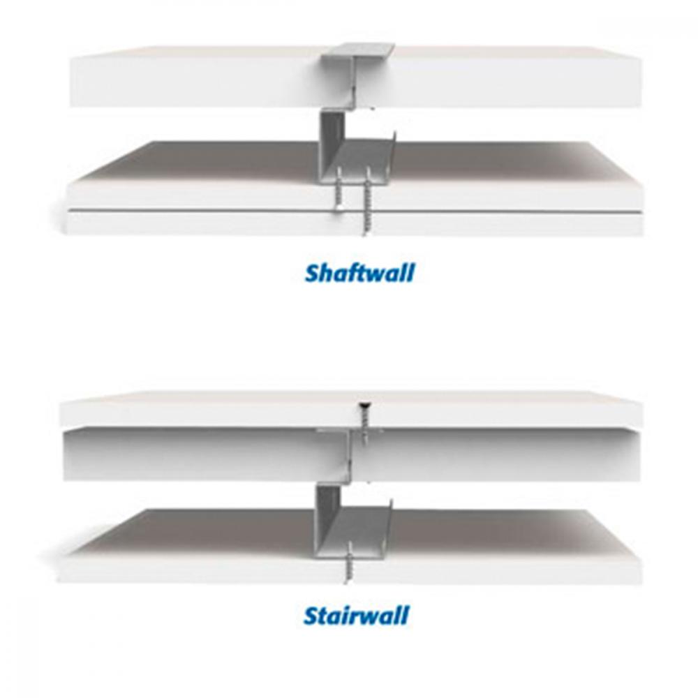
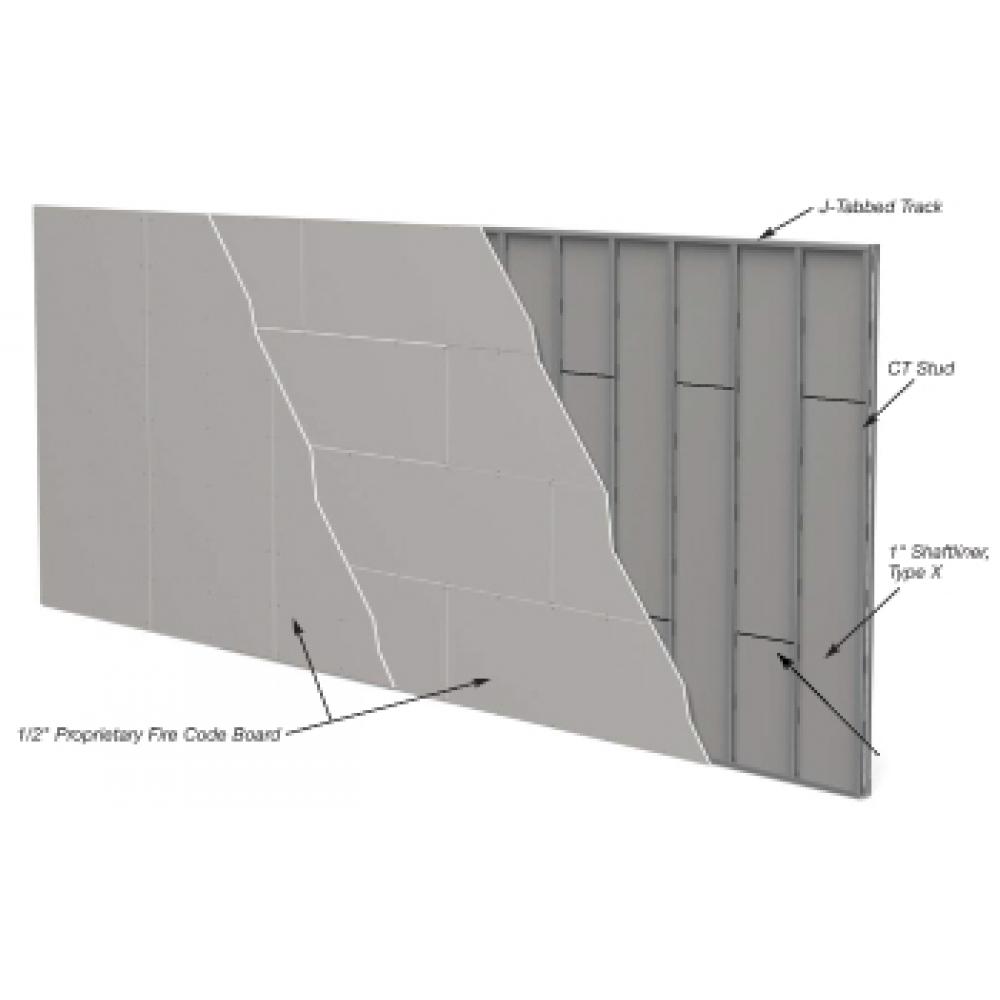
Shaftwall System consists of 1" shaftliner panels supported by 2-1/2", 4" or 6" C-T Studs and faced on one side with two layers of 1/2" fire code board.
Stairwall Systems are designed to enclose stairwalls, this system is finished on both sides with a single layer of 1/2" fire code board.
Shaftwall systems are interior nonload-bearing fire rated wall assemblies that provide critical, life safety, fire-resistant protection for elevator shafts, stairwells, vertical chases and mechanical enclosures. Shaftwalls in elevators and stairwells are one of the most important wall assemblies in a building. They provide the only means of evacuation from the building in an emergency. Vertical chases and mechanical enclosures keep vital communication, power, water, fresh air and exhaust systems intact when a fire occurs.
Cavity shaftwalls are constructed utilizing one of two methods: masonry/CMU or light-gauge steel and gypsum. Gypsum drywall shaftwall construction has become the preferred and most widely used shaftwall assembly. These shaftwalls are lightweight, install faster, and provide lower inplace costs. They also significantly reduce structural framing and foundation costs. Masonry shaftwalls in high-rise buildings historically weigh between 20 and 45 lbs. per square foot compared to gypsum assemblies that weigh between 10 and 13 lbs. per square foot.
In addition to substantial weight reduction, gypsum shaftwall assemblies can be installed from the exterior of the shaft at each floor, eliminating the need for scaffolding. Shaftwall installation is easy, quick and clean. Light-gauge steel and gypsum assemblies provide fast, lightweight, low-cost and high-performance assemblies.
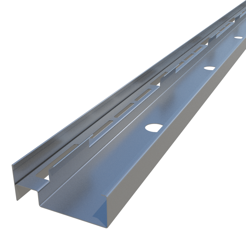
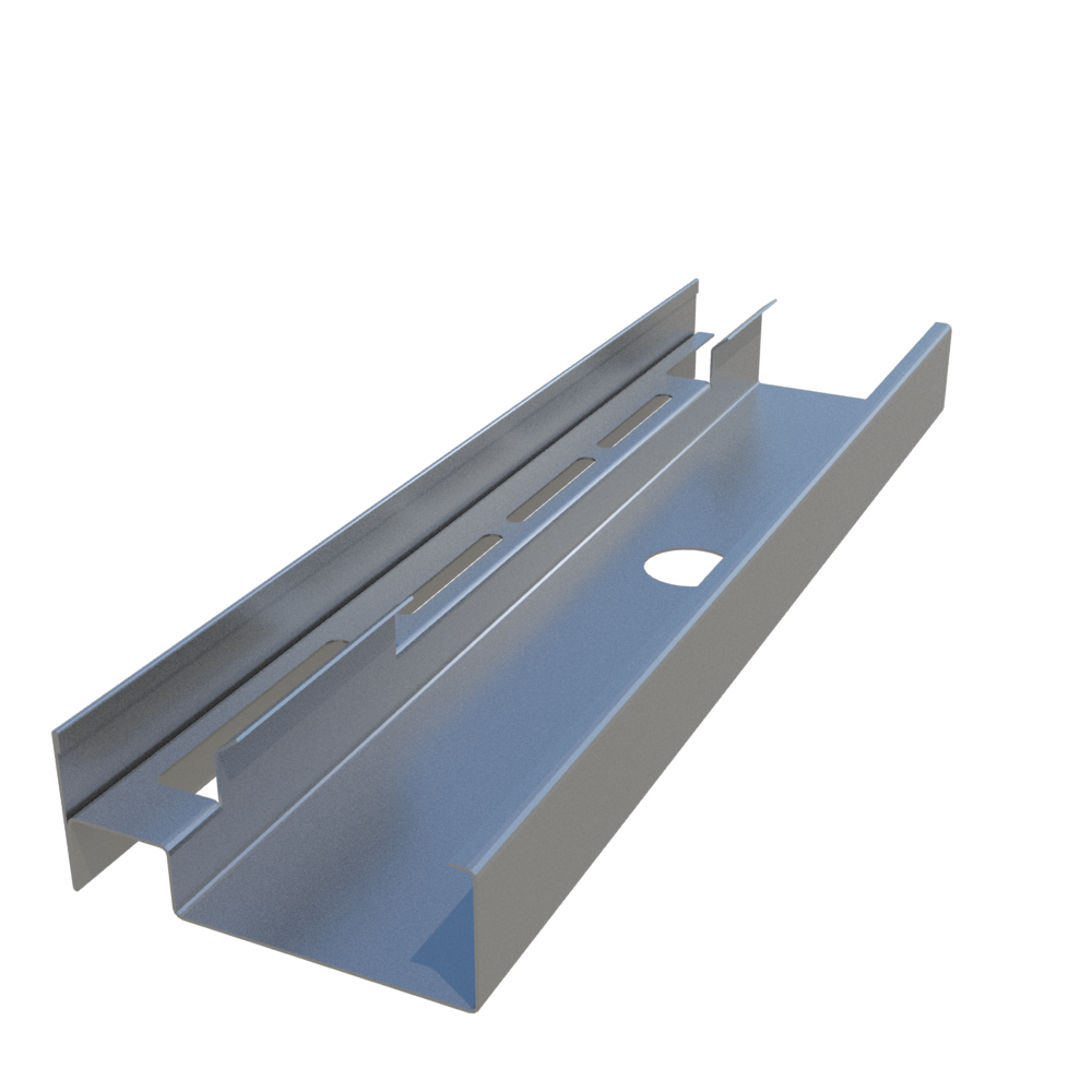
ClarkDietrich C-T Stud Profile
ClarkDietrich C-T Cavity Shaftwall Studs are rigid high-performance members engineered to maintain shaftwall integrity. C-T Studs are designed for use with 1" thick gypsum shaftliner panels. C-T Studs are friction-fitted between top and bottom J-Track. Gypsum shaftliner panels are inserted into the stud flanges. The flanges provide an airtight friction fit along the length of the panel. Studs are automatically spaced 24" o.c. maximum. The system is finished with fire rated gypsum board to complete and achieve the designated fire rating.
C-T Studs are available in 22mils (25ga), 33mils (20ga) and 43mils (18ga).
43mils (18ga) C-T Studs are only available in select markets (43 mils/18ga C- T Studs are for interior systems only)
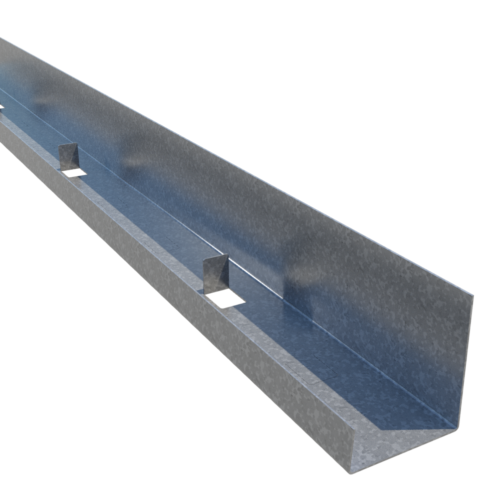
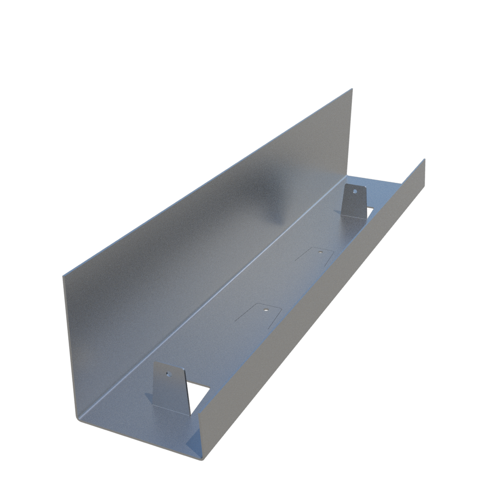
ClarkDietrich J-Tabbed Track Profile
ClarkDietrich J-Track is used at the floor and ceiling in shaftwall assemblies. C-T studs and gypsum shaftliner panels are friction fit between the top and bottom J-Tracks. J-Tracks have unequal legs. The longer leg (available in 2-1/4" and 3") is installed against the shaft. The leg provides a backstop for easy installation of the liner panel. Three-inch leg track is typically used as a jamb strut around closure details, including duct and door openings, abutments and intersections.
J-Tracks are available with optional "tabs" for ease of C-T Stud spacing.
C-T Stud Limiting Heights (Interior nonload-bearing)
Values below are listed in the ICC-ES Evaluation Report ESR-5050 and are for 2 hour rated wall systems only.
Click the below Member to view individual Tech Datasheet / Submittal
| Product Code Description | Deflection | 5 PSF | 7.5 PSF | 10 PSF | 15 PSF |
|---|---|---|---|---|---|
| 250CT-22 2-1/2" 22mils (25ga) | L/120 | 16'-10" | 13'-8" | 11'-10"* | 8'-6"* |
| L/240 | 11'-10" | 9'-10" | 8'-8" | 7'-3" | |
| L/360 | 9'-10" | 8'-3" | 7'-3" | 6'-2" | |
| 250CT-33 2-1/2" 33mils (20ga) | L/120 | 16'-10" | 14'-4" | 12'-11" | 11'-1" |
| L/240 | 12'-11" | 11'-1" | 9'-11" | 8'-7" | |
| L/360 | 11'-1" | 9'-6" | 8'-7" | 7'-5" | |
| 250CT-43 2-1/2" 43mils (18ga) | L/120 | 17'-11" | 15'-10" | 14'-6" | 12'-10" |
| L/240 | 14'-6" | 12'-10" | - | - | |
| L/360 | 12'-10" | - | - | - | |
| 400CT-22 4" 22mils (25ga) | L/120 | 21'-8" | 16'-6"* | 12'-5"* | 8'-3"* |
| L/240 | 16'-0" | 13'-7" | 12'-1" | 8'-3"* | |
| L/360 | 13'-7" | 11'-6" | 10'-4" | 8'-3"* | |
| 400CT-33 4" 33mils (20ga) | L/120 | 23'-0" | 21'-0" | 18'-7" | 15'-5"** |
| L/240 | 18'-7" | 15'-10" | 14'-1" | 12'-1" | |
| L/360 | 15'-10" | 13'-6" | 12'-1" | 10'-4" | |
| 400CT-43 4" 43mils (18ga) | L/120 | 25'-7" | 22'-2" | 20'-0" | 17'-4" |
| L/240 | 20'-0" | 17'-4" | 15'-8" | 13'-7" | |
| L/360 | 17'-4" | 15'-1" | 13'-7" | 11'-10" | |
| 43mils (18ga) only available in select markets (43mils/18ga is for interior systems only) | |||||
| 600CT-33 6" 33mils (20ga) | L/120 | 30'-3"** | 24'-9"** | 20'-6"* | 13'-8"* |
| L/240 | 26'-6" | 22'-2" | 19'-7" | 13'-8"* | |
| L/360 | 22'-2" | 18'-8" | 16'-7" | 13'-8"* | |
| 600CT-43 6" 43mils (18ga) | L/120 | 36'-5" | 30'-8" | 27'-3" | 23'-2" |
| L/240 | 27'-3" | 23'-2" | 20'-8" | 17'-8" | |
| L/360 | 23'-2" | 19'-9" | 17'-8" | --- | |
| 43mils (18ga) only available in select markets (43mils/18ga is for interior systems only) | |||||
* Reduced for End Reaction capacity
** Reduced for Flexural Strength Capacity
- The values in this table are based on testing per ICC-ES AC86 and ASTM E72 and represent the limiting height capacity for strength using a 1.5 Safety Factor.
- Limiting Height values shown, were assessed from the lowest Flexural Stength value of gypsum tested.
Table above is for 2 hour rated wall systems only
Review all Shaftwall Installation Procedures & Product Limitations
(18ga only available in select markets)
Use our ClarkDietrich iTools (C-T Stud Shaftwall Lookup Tool)
to quickly find the system that meets your specs
For Interior Corridor Ceilings
2 Hour Wall with (2) layers 1/2" Type C + (1) 1" Shaft Liner
| Product Code / Stud Depth | Gauge | L/120 | L/180 | L/240 | L/360 |
|---|---|---|---|---|---|
| 250CT-22 / 2-1/2" | 22mils (25ga) | 8'-8" | 8'-8" | 8'-6" | 7'-5" |
| 250CT-33 / 2-1/2" | 33mils (20ga) | 10'-6" | 10'-6" | 9'-10" | 8'-7" |
| 400CT-22 / 4" | 22mils (25ga) | 11'-8" | 11'-8" | 11'-8" | 10'-8" |
| 400CT-33 / 4" | 33mils (20ga) | 14'-3" | 14'-3" | 14'-1" | 12'-4" |
| 400CT-43 / 4" | 43mils (18ga) | 19'-1" | 16'-8" | 15'-2" | 13'-3" |
| 600CT-33 / 6" | 33mils (20ga) | 18'-9" | 18'-9" | 18'-9" | 16'-10" |
| 600CT-43 / 6" | 43mils (18ga) | 22'-9" | 22'-9" | 20'-9" | 18'-2" |
2 Hour Wall with (2) layers 5/8" Type X + (1) 1" Shaft Liner
| Product Code / Stud Depth | Gauge | L/120 | L/180 | L/240 | L/360 |
|---|---|---|---|---|---|
| 250CT-22 / 2-1/2" | 22mils (25ga) | 8'-2" | 8'-2" | 8'-2" | 7'-2" |
| 250CT-33 / 2-1/2" | 33mils (20ga) | 9'-11" | 9'-11" | 9'-6" | 8'-3" |
| 400CT-22 / 4" | 22mils (25ga) | 11'-0" | 11'-0" | 11'-0" | 10'-3" |
| 400CT-33 / 4" | 33mils (20ga) | 13'-6" | 13'-6" | 13'-6" | 11'-10" |
| 400CT-43 / 4" | 43mils (18ga) | 18'-5" | 16'-1" | 14'-7" | 12'-9" |
| 600CT-33 / 6" | 33mils (20ga) | 17'-9" | 17'-9" | 17'-9" | 16'-3" |
| 600CT-43 / 6" | 43mila (18ga) | 20'-5" | 20'-5" | 20'-0" | 17'-6" |
- Values above are listed in the ICC-ES Evaluation Report ESR-5050
- Review all Shaftwall Installation Procedures & Product Limitations
- (43mils/18ga only available in select markets) 18ga is for interior systems only
- Dead Load of assembly ONLY is considered.
- Not designed to carry any Live Loads, Mechanical equipment, Storage Loads or Lighting.
- Studs must be one piece, full span.
- Minimum base steel thickness is 95% of design thickness.
- Verify details of construction for specific assembly to achieve required fire resistance rating and code requirements.
- Horizontal corridor use permitted per IBC section 708.4 Continuity, Exception 3 and Exception 3 Commentary.
ClarkDietrich Shaftwall Fire-Rated Information
Shaftwall Intertek Fire-Rated Design Listings:
Intertek Spec ID: 26661 - ClarkDietrich Steel 'C-T' Stud and J-Tabbed Track Fire-resistance-rated Shaftwall and Stairwall Wall Assemblies
- Intertek Design No. CD/WA 120-01 - Non-Load Bearing Shaftwall 2 Hour Assembly
- Intertek Design No. CD/WA 120-02 - Non-Load Bearing Stairwall 2 Hour Assembly
- Intertek Design No. CD/WA 60-01 - Non-Load Bearing Shaftwall 1 Hour Assembly
(All infomation below is also listed in the ICC-ES Evaluation Report ESR-5050)
Two-Hour Cavity Stairwall (Non-Load Bearing)
- A minimum 25 gauge, 2-1/2" deep ClarkDietrich floor and ceiling J-Tracks.
- A minimum 25 gauge, 2-1/2" deep ClarkDietrich CT-Studs, spaced 24" o.c. centered between the top and bottom J-Tracks with a minimum 1/2" clearance from the web of the J-Tracks.
- Two (2) layers of 1/2" Type C or 5/8" Type X gypsum board, one layer per side. The face layers should be installed parallel to each face of the framing members with #6 x 1" Type S drywall screws 12" o.c. (Note - Use Type S-12 drywall screws for 20 gauge), 1" from board ends at joints and a minimum of 3/8" from board edges. All edge and end joints should be offset from the base layer minimally 6".
- 1" thick fire rated gypsum (Type X). The 1" liner panels should be cut 1" less than the opening height. At the ends the 1" liner panel may be retained by bending the J-runner tabs 90 degrees. If the J-Tracks are used at end walls and have the optional "tabs", bend the tabs 90 degrees, or the 1" liner panels need to be fastened at the ends with 1-5/8" Type S screws spaced 12" o.c.
Two-Hour Cavity Shaftwall (Non-Load Bearing)
- A minimum 22mils (25 gauge), 2-1/2" deep ClarkDietrich floor and ceiling J-Tracks.
- A minimum 2-1/2" deep ClarkDietrich C-T Studs 22mils (25 gauge), centered between the top and bottom J-Tracks with a minimum 1/2" clearance from the web of the J-Tracks.
- The base layer of 1/2" Type C or 5/8" Type X gypsum board should be installed horizontally to the framing members with #6 x 1" Type S drywall screws, 24" o.c., starting 3" maximum from the top and bottom. The butt joint should be centered on a stud flange.
- The face layer of 1/2" Type C or 5/8" Type X gypsum board should be installed vertically to the framing members with 1-5/8" Type S drywall screws, maximum 12" o.c. starting 6" from the top and bottom. The vertical edge and butt joints should be offset to different studs from the base layer. The horizontal butt joint in the face layer should be offset 18" from the horizontal edge joint in the base layer.
- 1" thick fire rated (Type X) gypsum liner panel. The 1" liner panels should be cut 1" less than the opening height. At the ends of the partition the 1" liner panel may be retained by bending the J-runner tabs 90 degrees, or the 1" liner panels need to be fastened at the ends with 1-5/8" Type S screws spaced 24" o.c.
Two-Hour Corridor Ceilings and Stair Soffits Horizontal Assembly
- The Two-Hour assembly is constructed as described above in the Two-Hour Shaftwalls. See C-T Stud Horizontal Span Tables for stud size, thickness and maximum spans. See Installation procedures for assembly details and specifications.
SOUND RATINGS : SHAFTWALL / STAIRWALL
The Shaftwall / Stairwall assemblies and their components mentioned in the ICC-ES Evaluation Report ESR-5050 have been tested in accordance with ASTM E90 (90) and ASTM E413 (87). The shaftwall assemblies were evaluated for sound transmission loss values. The values are only valid if the construction of the assemblies follow the construction as noted in the test reports. When the assemblies are installed in the same manner as noted in the test reports the assembly will have a minimum STC (Sound Transmission Class) rating of 50.
Full list of Sound Ratings
| STC Rating | Test Number | Wall Detail | Description |
|---|---|---|---|
| 38 | (Shaftwall #1) | C-T studs 24" o.c. in J-Track. Friction fitted 1" shaftliner panels into "T" section. Base layer of 1/2" gypsum wallboard attached horizontally to "C" section with 1" screws spaced 24" o.c. and 3" from top and bottom tracks. Face layer attached vertically with 1-5/8" screws spaced 12" o.c. and 6" from top and bottom tracks. Face layers are finished with paper tape and joint compound. | |
| 44 | (Shaftwall #2) | Same as Shaftwall #1 with 3 pcf mineral wool insulation cavity. | |
| 53 | (Shaftwall #3) | Same as Shaftwall #2 with single leg 25 gauge resilient channel applied horizontally and spaced 24" o.c. attached with (1) 3/8" screw at each stud. | |
| 39 | (Stairwall #1) | C-T studs 24" o.c. in J-Track. Friction fitted 1" shaftliner panels into "T" section. A face layer of 1/2" gypsum wallboard applied vertically, attached to each side of C-T stud. Wallboard is attached with 1" screws spaced 12" o.c. and 6" from top and bottom tracks. Face layers are finished with paper tape and joint compound. | |
| 43 | (Stairwall #2) | Same as Stairwall #1 with 3 pcf mineral wool insulation in cavity. | |
| 51 | (Stairwall #3) | Same as Stairwall #2 with single leg 25 gauge resilient channel applied horizontally and spaced 24" o.c. attached with (1) 3/8" screw at each stud. |
INSTALLATION REQUIREMENTS
*** Reference design assemblies and gypsum board manufacturer for details of the wall system ***
- Reference ICC-ES Evaluation Report ESR-5050 for detailed requirements of construction of ShaftWall assembly.
- In structural steel-frame construction, install perimeter J-Track sections before applying spray-on fireproofing.
- Pre-cut C-T studs 3/4" less than the opening’s height between top and bottom J-Track.
- Items to be anchored to the wall (cabinets, sinks, handrails, etc.) should be fastened to steel plates secured behind or between layers of 1/2" gypsum.
- Use Type-S screws for 25-gauge steel framing. Use type S-12 screws for 20-gauge (or heavier) steel framing.
- It is important that the job engineer approve the type, size, and maximum spacing of track fasteners to meet the design load requirements.
LIMITATIONS OF USE
- DO NOT STACK WALLS
- Shaftwall assemblies are designed as interior non-load-bearing partitions only.
- Do not install in areas which will be adjacent to occupancies of unusually high moisture conditions.
- C-T Studs cannot be spliced. They must be installed full length and one piece. J-Tracks when not attached to the structure shall not be spliced. Do not attach the J-Tracks to the C-T Studs unless noted otherwise by the manufacturer's installation procedures.
- All Shaftwall members shall be simple span members with no intermediate supports.
- Provide control joints so that maximum length of continuous partition is 30 feet. Wherever possible, the partition control joints should coincide with those in the building structure.
- Elevator door frames should be supported independently of the shaftwall. However, interfacing of elevator frame to shaftwall system may require attachment with jamb clips and/or grouting.
- Where penetrations occur in the partitions, additional reinforcement at corners may be necessary to distribute stresses if control joints are not used and if excessive loads need to be supported.
- To prevent air movement and resulting whistling, the partition perimeters, as well as all penetrations, should be effectively sealed with a non-hardening sealant.
- Finishing of all joints in face layers should be done within temperature limitations of the specific joint treatment used.
- Not recommended for use as an unlined HVAC supply shaft or duct.
- Hollow cavities must be fire stopped at each floor.
- Openings and Penetrations in Shaftwall/Stairwell systems: As tested per ASTM E119/UL 263, these systems do not contain any Openings or Penetrations.
- All Opening and Penetration covering assemblies must be approved for use per Section 713.7 and 713.8 of the 2018 IBC.
- Any Opening or Penetration framing detail provided here is not a tested detail, but a generally accepted practice coinciding with approved assemblies in noted a. above.
- C-T Studs are Nonloadbearing, and where an Opening or Penetration is required the J-Track must be supported by a designed structural element.
- All Opening or Penetration fire rated assemblies require independent structural support, as the Shaftwall/Stairwell systems are not designed or tested under this condition.
LOCATION OF GYPSUM BOARD JOINTS
- Shaftliner panels may be abutted (spliced or stacked) within the cavity as shown in the drawing to the right. The shorter panel should be at least two feet long or of sufficient length to engage two stud tabs on each panel edge. NOTE: In addition, some local codes may also require that these splices be back-blocked with a 12" x 24" piece of gypsum even though the tests were preformed with these joints unblocked. Also, back blocking may be done with the C-T Stud of proper length and placed horizontal. Please check with your local jurisdiction.
- For the shaftwall system, finished one side, install the first layer of 1/2" fire code board horizontally with 1" Type-S screws spaced 24" o.c. and 3" from all edges. The horizontal joints must be offset from any splice joints in the shaftliner panels by at least 12".
- The face layer, also fire code board, installed parallel to framing with 1-5/8" Type-S screws spaced 12" o.c. at all framing members maintaining a 6" edge distance. All edge and end joints should be offset from the base layer by 24".
- For the stairwall system, finished both sides, each side must be installed vertically with 1" Type-S Screws spaced 12" o.c. maintaining a 3" distance from edge. Offset edges and ends on opposite sides 24" o.c.
- Caulk all perimeter edges and abutments with dissimilar materials, and penetrations in the facing layers with a non-hardening flexible sealant.
- All joints on face layers are to be taped and finished and fastener heads finished with joint compounds meeting ASTM C475 standard specification.
INSTALLATION - VERTICAL SHAFTWALLS
- Layout per construction drawings. Secure J-Track as perimeter framing and plumb to ceiling, floor and sides. Attached with suitable fasteners, spaced not more than 24" o.c. Apply a bead of non-hardening, flexible sealant to the perimeter.
- Pre-plan the stud layout 24" o.c. and adjust the spacing at either end so the end studs will not fall closer than 12" from the end.
- Erect the first 1" Shaftliner panel, cut 3/4"-1" less than the total height of the framed section. Plumb the panel against the web of the J-Track and bend out optional tabs in J-Track to secure panels in place.
- Insert C-T Stud, cut 3/4" less than overall height, into the top and bottom J-Tracks and fit tightly over previously installed 1" panel. Allow equal clearance between top and bottom J-Track.
- Install the next 1" Shaftliner inside the J-Track and within the tabs of the C-T stud.
- Progressively install succeeding studs and panels as described above until the wall section is enclosed. The final panel section may be secured with tabs from the J-Track at 12" o.c.
- Where wall heights exceed the standard or available length of Shaftliner panels, the panels may be cut and stacked with joints occurring within the top or bottom third points of the wall. Joints of adjacent panels should be alternately staggered to prevent a continuous horizontal joint. Gypsum panels must engage a minimum of 2 tabs.
- C-T Studs cannot be spliced. They must be installed full height, one piece.
- For doors, ducts or other large penetrations or openings, install J-Track as perimeter framing. Use 20-gauge track with a 3" back leg for elevator doors and block cavity with 12" wide gypsum filler strips for doors exceeding 7'-0" height.
INSTALLATION - HORIZONTAL SHAFTWALLS FOR CORRIDOR CEILINGS
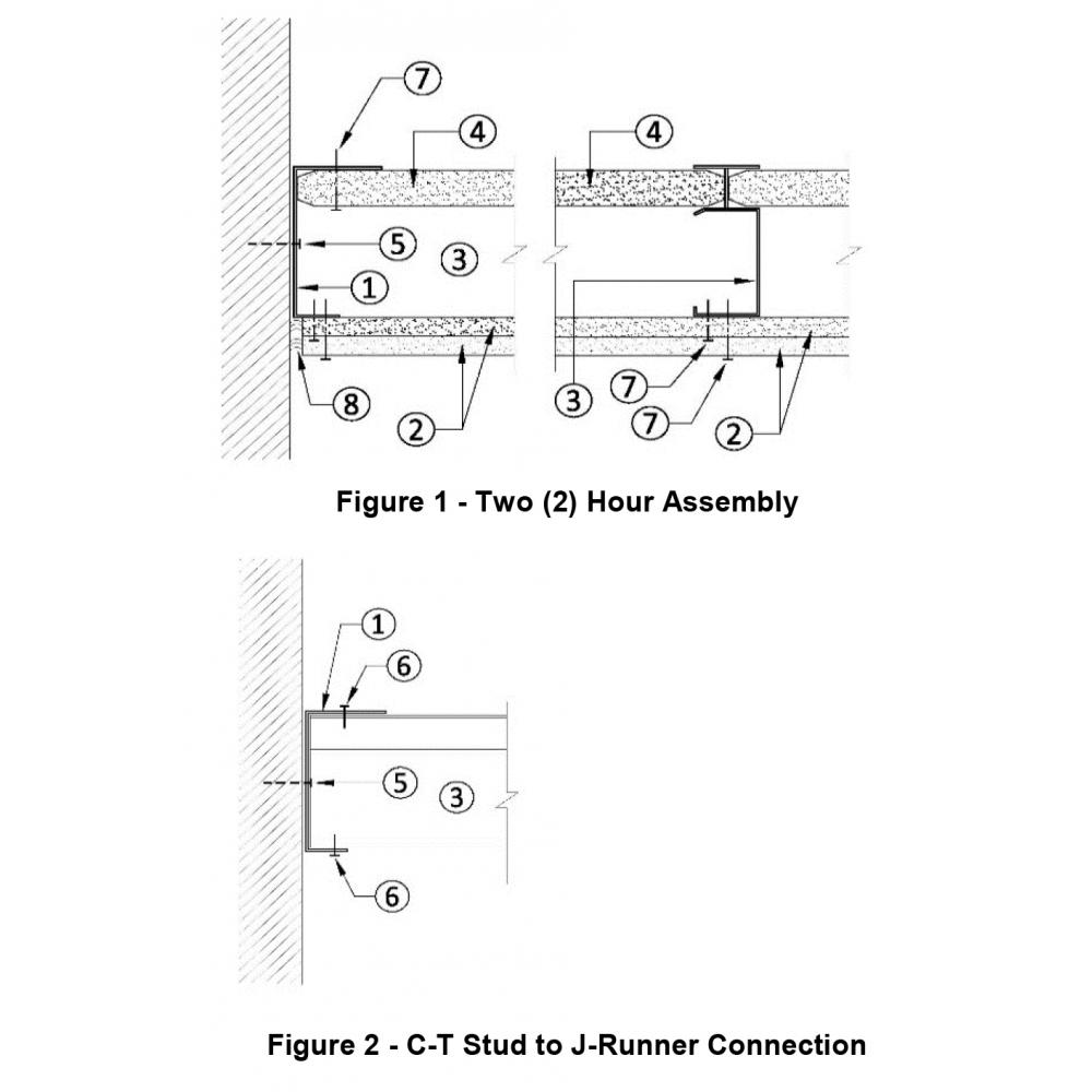
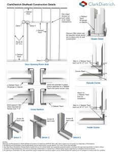
Two Hour Horizontal Shaft Wall Assembly Instructions – See Figures 1 - 2 to the right.
- Horizontal ceiling applications are not designed for any live load, mechanical equipment, or for any storage load.
- Maximum spans are as shown in Table 2.
- The corridor ceiling or stair soffit horizontal assembly is constructed from the floor.
- J-Track (Item ①) is first secured to all corridor walls or stair stringer framing around the perimeter of the ceiling or stair soffit to be protected.
- The J-Track (Item ①) will be at a minimum:
33mil, 0.0346-in (20ga) thickness for 25ga and 20-ga C-T studs. (Item ③)
43mil, 0.0451-in (18ga) thickness for 18ga C-T studs. (Item ③) - The J-Track (Item ①) is positioned with the shorter 1-in long leg of the track facing the floor.
Fasteners are placed through the web of the J-Track to the supporting structure
Mechanical fasteners shall be spaced a maximum of 24-in on-center along the length of the J-Track to the supporting structure.
The track to perimeter wall connection (Item ⑤) shall be detailed by the designer to provide a minimum of 200 lbs of shear capacity for every C-T stud location. - 1-inch thick x 24-inches-wide gypsum shaft liner panels (Item ④) are inserted in the J-Tracks (Item ①) towards the ceiling (2-in leg of the J-Track).
Measure the overall dimensions of the opening and determine if the first 1-in shaft liner installed should be cut lengthwise so that the final shaft liner panel is not less than 8-in in width.
The first liner panel will be secured to the J-Track by using #6 x 1-5/8-in drywall screws 12-in on-center and at each end through the longer leg of the J-Track. - C-T stud (Item ③) of the required depth and thickness will positioned so that it secures the free edge of the first shaft liner panel within the “T” portion of the C-T stud.
- Do not splice C-T studs. Use only full length pieces of the proper length.
- Both ends of the C-T stud (Item ③) will be secured to both flanges of the J-Track using a minimum ½” long #8 pan-head screw (Item ⑥).
- The sequence of alternating placement of shaft liner panels (Item ④) and C-T studs (Item ③) will continue with each C-T stud engaging the long edges of the 1-in shaft liner panels.
- The end of each 1-in shaft liner panel within the perimeter J-Track is fastened to the J-Track flange with three #6 x 1 5/8” Type S screws (12-in on-center).
- Liner panels may be cut; butt the factory ends of the liner panels. The butt joints shall occur within the outermost one third points of the span. Joints in adjacent liner panels shall be alternately staggered to prevent a continuous joint.
- Secure the last liner panel to the tabbed J-Track by using #6 x 1-5/8-in drywall screws 12-in on-center and at each end through the longer leg of the J-Track.
- For a two-hour assembly two layers of 1/2" Type C or 5/8" Type X gypsum board (Item ②) should be installed at right angles to the framing members. Install the inner layer with #6 (Item ⑦) x 1" Type S drywall screws, 24" o.c., starting 3" maximum from the ends of the C-T studs. Butt joint of adjacent panels should be centered on a stud flange. Install the outer layer of 1/2" Type C or 5/8" Type X gypsum board with #6 (Item ⑦) x 1-5/8” Type S drywall screws, 12" o.c. in the field and at the perimeter. Offset the board joints a minimum of one stud spacing (24”) between layers.
- Caulk the perimeter edges and abutments with dissimilar materials and any penetrations with a non-hardening flexible sealant (Item ⑧).
- All joints on the outer layer shall be taped and finished and fastener heads finished with joint compounds meeting ASTM C474.
Code Approvals & Performance Standards
- AISI S100-16 (2020) w/S2-20 North American Specification for the Design of Cold-Formed Steel Structural Members
- AISI S220-20 North American Standard for Cold-Formed Steel Framing - Nonstructural Members
- (Compliant to ASTM C645 , but IBC replaced with AISI S220 in IBC 2015)
- Section A3 Material - Chemical & mechanical requirements (Referencing ASTM A1003/A1003M)
- Section A4 Corrosion Protection (Referencing ASTM A653/A653M)
- Section C Installation - (Referencing ASTM C754)
- ICC-ES ESR-5050 Shaftwall Systems
- Intertek SPEC ID 26661 Shaftwall and Stairwall Wall Assemblies
- SDS For ASTM A1003 Steel Framing Products For Interior Framing, Exterior Framing and Clips/Accessories
- Meets or exceeds the requirements as stated in Section 703.2 of the 2018 International Building Code for Fire Resistance Ratings of building elements, components, or assemblies with the test procedures set forth in ASTM E119.
- Meets or exceeds the requirements as stated in Section 703.2.1 of the 2018 International Building Code for Nonsymmetrical wall construction of Interior Walls and partitions shall be tested with both faces exposed to the furnace and the assigned fire-resistance ratings shall be the shortest durations obtained from two tests conducted in compliance with ASTM E119.
- Meets the requirements for Fire Resistance ratings for shaft enclosure of not less than 2 hours as stated in Section 713.4 of the 2018 International Building Code.
- Meets the requirements for construction for shaft enclosures as fire barriers in accordance with Section 707 of the 2018 International Building Code.
- Meets or exceeds the requirements as stated in Section 2203.1 of the 2018 International Building Code for Identification and Protection of Steel for Structural Purposes
- Meets or exceeds the requirements as stated in Section 2203.2 of the 2018 International Building Code in regards to painting of structural steel members as required in AISI S200 & S100.
PRoduct submittal SHeets
Click the below Product Code to view Submittal/Tech Datasheet.
| Product Code | Description |
|---|---|
| 250CT-22 | 2-1/2", 21mils (25ga) C-T Stud Shaftwall Sytem |
| 250CT-33 | 2-1/2", 33mils (20ga) C-T Stud Shaftwall Sytem |
| 250CT-43 | 2-1/2", 43mils (18ga) C-T Stud Shaftwall Sytem |
| 400CT-22 | 4", 21mils (25ga) C-T Stud Shaftwall Sytem |
| 400CT-33 | 4", 33mils (20ga) C-T Stud Shaftwall Sytem |
| 400CT-43 | 4", 43mils (18ga) C-T Stud Shaftwall Sytem |
| 600CT-33 | 6", 33mils (20ga) C-T Stud Shaftwall Sytem |
| 600CT-43 | 6", 43mils (18ga) C-T Stud Shaftwall Sytem |
ClarkDietrich SubmittalPro®
Submittal sheets for the exact product you're looking for can be created by using ClarkDietrich's SubmittalPro® Product Submittal System.
- Contact ClarkDietrich Technical Services at 888-437-3244 for any questions about creating product submittals or using SubmittalPro.